FiberBasix 50, ELS-50, EPM-50

FiberBasix 50 – handheld testers

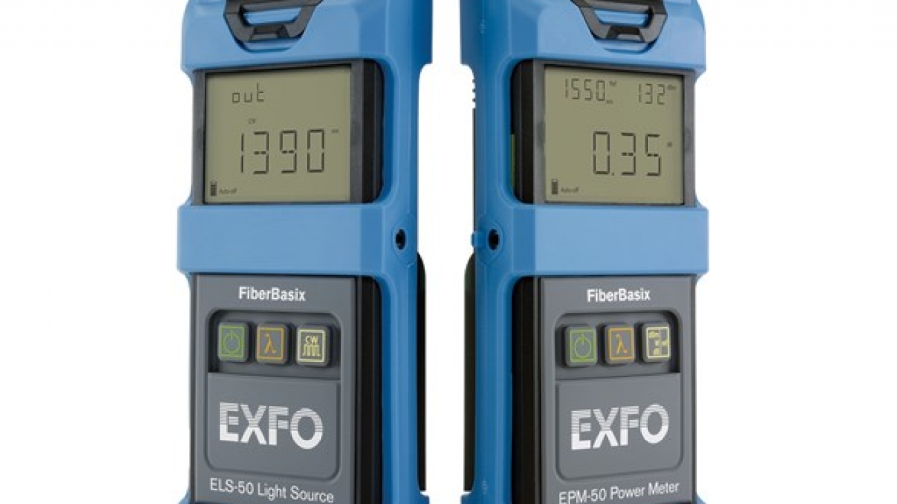
EXFO’s FiberBasix 50 series meets your basic day-to-day test requirements while helping you stay within budget. These worry-free, straightforward handheld testers enable accurate measurement of signal attenuation during fiber-optic cable installation.

The FiberBasix 50 series includes two highly convenient instruments:

  • The ELS-50 Light Source, combining up to three wavelengths in a single configuration
  • The EPM-50 Power Meter, which offers high accuracy and referencing capabilities

An FTTx test solution

These products are part of EXFO’s series of FTTx optical test products. They allow for the testing of passive optical networks (PONs) at the three main wavelengths (1310, 1490 and 1550 nm) used in fiber-to-the-home (FTTH) and fiber-to-the-premises (FTTP) networks and comply with the ITU-T G.983 and G.984 Recommendation series and the IEEE 802.3ah standard.

ELS-50 light source: multiwavelength capability

EXFO’s ELS-50 Light Source provides excellent stability and high measurement accuracy for up to three singlemode wavelengths or two multimode wavelengths. It is the perfect complement to the FiberBasix 50 EPM-50 Power Meter when it comes to measuring attenuation on fiber-optic links.

EPM-50 power meter: high accuracy and easy referencing

The EPM-50 Power Meter provides highly accurate power measurements, as well as reference value setting capabilities. It offers power autonomy of 300 hours, for reliable, long-lasting performance in the field.

fls-110_1

FLS-110 – optical source

The FLS-110 Optical Source is a handheld polarized source—ideal for field PMD measurements. This broadband LED (typically 65 nm  in the C band) is especially suited to PMD measurements using the FTB-5500B PMD Analyzer.

Practical Features

The FLS-110 offers CW and 2 kHz modulation for fiber identification, complete status indicators, a low-battery indicator and an Auto-Off function. The unit is housed in a sturdy, waterproof case surrounded by a shock-absorbing holster that protects the instrument in tough field conditions.

Choose between the 1310 nm or the 1550 nm LED models. Both units feature high and low power levels to maximize battery life.

Power to Spare

The FLS-110 features three complementary power sources for extended operation. When the rechargeable NiCd battery runs low, the unit automatically switches to the 9 V alkaline battery backup. An AC adapter/charger is also supplied for continuous operation.

fls-140_1

FLS-140 – visual fault locator

The FLS-140 is the easiest way to identify optical fibers from end to end and locate polished connector endfaces. Its red laser shines through most yellow-jacketed optical fibers to help you pinpoint breaks, bends, faulty connectors, splices and other causes of signal loss. It has a reach of up to 5 km. The convenient FLS-140 locates faults visually by creating a bright red glow at the exact location of the fault on singlemode or multimode optical fibers.

Compact design

With a pocket-size pen-style design, this visual fault locator can easily be carried anywhere. Thanks to its anodized aluminum casing, this long-lasting and lightweight tool is the complementary tool of choice for any fiber-testing field technician.

Cost effective

The FLS-140’s extremely high efficiency guarantees prolonged operation with two standard AAA alkaline batteries, typically providing 40 hours of uninterrupted operation.

Priced to accommodate the tightest budgets, the FLS-140 is a truly affordable way to locate faults in OTDR dead zones. Its effectiveness justifies purchasing one for just about every fiber technician.

fls-240_1

FLS-240 Pocket Pal – visual fault locator

The FLS-240 Pocket Pal Visual Fault Locator is a straightforward solution for identifying breaks, bends, faulty connectors or splices, as well as other causes of signal loss. It can detect faults over distances of up to 5 km. The FLS-240 visually locates faults by creating a bright red glow at the exact location of the fault on singlemode or multimode fibers.

Robust design

To ensure ruggedness, the Pocket Pal features rubber seals, a fully enclosed laser head and a long-lasting On/Off switch. It has been tested to provide reliable operation under intensive use and harsh conditions.

fls-300_front_2000x1667

FLS-300 – light source

With up to three singlemode wavelengths on a single port, or four wavelengths (two multimode, and two singlemode) on two ports, the FLS-300 is the most versatile, complete light source available.

An FTTx test solution

This product is part of EXFO’s series of FTTx optical test products. It allows for the testing of passive optical networks (PONs) at the three main wavelengths (1310, 1490 and 1550 nm) used in fiber-to-the-home (FTTH) and fiber-to-the-premises (FTTP) networks and complies with the ITU-T G.983 and G.984 Recommendation series and the IEEE 802.3ah standard.

Auto-wavelength recognition

The FLS-300 Light Source can transmit with a wavelength-identification digital encrypted protocol, so that any compatible unit—the FPM-300 Power Meter and the FOT-300 Optical Loss Test Set—can automatically use the proper calibration parameters. This feature reduces the need for communication between the two technicians and decreases the potential for error.

Distant referencing

Signal encrypting can also give the receiving end information on the power to be used as reference, helping ensure efficient referencing, even when the two units are far apart.

fls-600_front_0046_update-2020_2000x1667

FLS-600 – light source

Part of EXFO’s 600 handheld series, the FLS-600 Light Source is designed for first-class versatility. Choose among laser, LED models, as well as various wavelength options. What’s more, you can save time by building a list of your “favorite” wavelengths and only sweeping through these wavelengths when testing.

Automatic wavelength switching

Using the FLS-600 in Auto-Switching Mode allows to automatically toggle between available wavelengths. When using this source with a compatible power meter (FPM/FOT-600), the latter recognizes the wavelength in use and switches to the proper calibration parameter.

Distant referencing

Signal encrypting can also give the receiving-end information on the power to be used as reference, helping ensure efficient referencing, even when the two units are far apart.

FTTx-ready

EXFO’s FLS-600 allows for the testing of passive optical networks (PONs) at 1310 nm, 1490 nm and 1550 nm, the three wavelengths recommended by the ITU-T (G.983.3) for PONs.

Rugged and versatile

Like all EXFO portable instruments, the FLS-600 is built for ruggedness, perfect for the harshest test conditions. It also features a backlit keypad/LCD , for easy operation in darker environments.

encircled-flux_2000x1667

FLS-600 NS-1548 – encircled flux compliant light source

Encircled Flux (EF) is a new standard that defines how to control the source launch conditions as specified in TIA-526-14-B and IEC 61280-4-1 Ed. 2.0.

Whether for an expanding enterprise business or a large-volume data center, the new high-speed data networks built with multimode fibers are running under tighter tolerances than ever before.

These multimode fibers are the trickiest links to test because the results depend greatly on each device’s output conditions. Testing with different equipment often returns different test results, sometimes higher than the budget loss itself. This may mislead the technician or make it impossibleto locate the fault, resulting in unsuccessful turnups or a longer network downtime. Now, cable installers can rely on their tier-1 loss results to perform tier-2 troubleshooting, and do so with maximum accuracy and utmost confidence of finding the actual problem.

Consistency and repeatability

Whether built-in or packaged in the external launch conditioner, EXFO tunes each EF-compliant device to perfection in-house, ensuring that every unit meets the EF templates for both 850 and 1300 nm at 50 μs. This allows technicians and contractors to obtain reliable, consistent and repeatable results during construction, thus eliminating doubts and uncertainty. The test documentation that is generated will also help future-proof networks. When upgrades are needed, technicians and contractors will know quickly which circuits have to be activated, thereby saving time and troubles down the line.

The necessity of launch and receive cables

Link characterization is often performed using an OTDR. However, despite the fact that an OTDR has the shortest dead zones, the way loss is measured in a link means that to characterize the first and last connectors, an OTDR needs a launch cable, also called a pulse suppressor box.

The reason for this is that the loss associated with an event is the difference between the backscattering levels measured before and after the event. To account for the dead zone, a backscattering level must be obtained before the first connector. This requires inserting a length of fiber between the OTDR port and the first connector of the fiber under test. At the other end, the same lengthof fiber is inserted after the last connector.

In order to measure the loss of the first and last connectors, it is important to use launch and receive cables. The SPSB-EF has an internal 30-meter fiber that allows complete end-to-end loss while still maintaining the EF launch conditions up to the first connector of the link. By complying with the EF standards, faulty connectors are easily located when troubleshooting high-speed multimode links.