FiberBasix 50, ELS-50, EPM-50

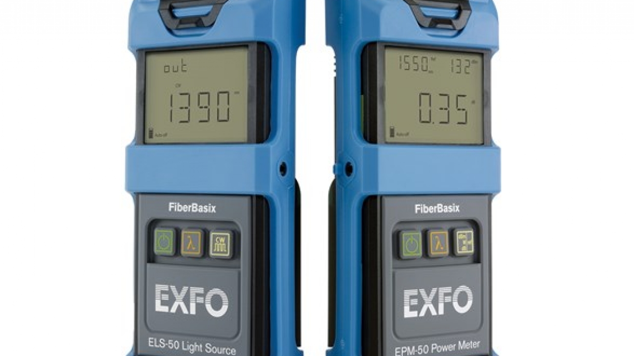
FiberBasix 50 – handheld testers

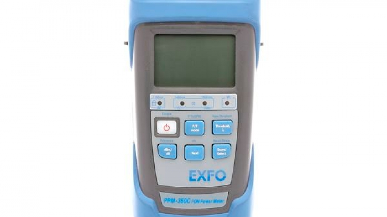
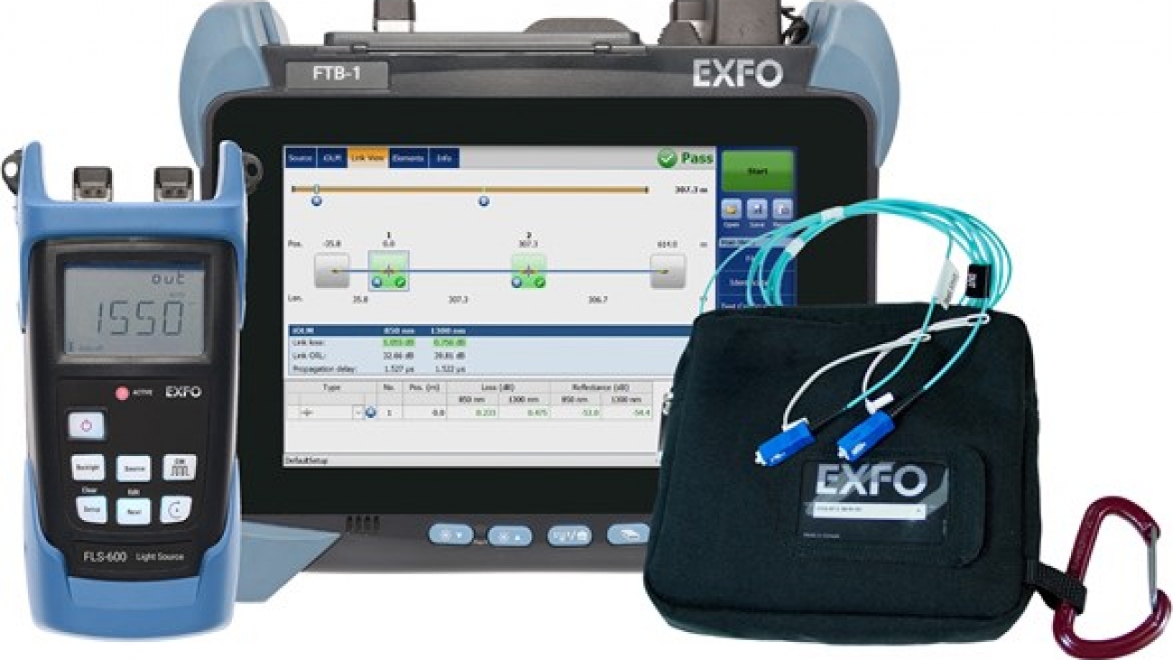
EXFO’s FiberBasix 50 series meets your basic day-to-day test requirements while helping you stay within budget. These worry-free, straightforward handheld testers enable accurate measurement of signal attenuation during fiber-optic cable installation.

The FiberBasix 50 series includes two highly convenient instruments:

  • The ELS-50 Light Source, combining up to three wavelengths in a single configuration
  • The EPM-50 Power Meter, which offers high accuracy and referencing capabilities

An FTTx test solution

These products are part of EXFO’s series of FTTx optical test products. They allow for the testing of passive optical networks (PONs) at the three main wavelengths (1310, 1490 and 1550 nm) used in fiber-to-the-home (FTTH) and fiber-to-the-premises (FTTP) networks and comply with the ITU-T G.983 and G.984 Recommendation series and the IEEE 802.3ah standard.

ELS-50 light source: multiwavelength capability

EXFO’s ELS-50 Light Source provides excellent stability and high measurement accuracy for up to three singlemode wavelengths or two multimode wavelengths. It is the perfect complement to the FiberBasix 50 EPM-50 Power Meter when it comes to measuring attenuation on fiber-optic links.

EPM-50 power meter: high accuracy and easy referencing

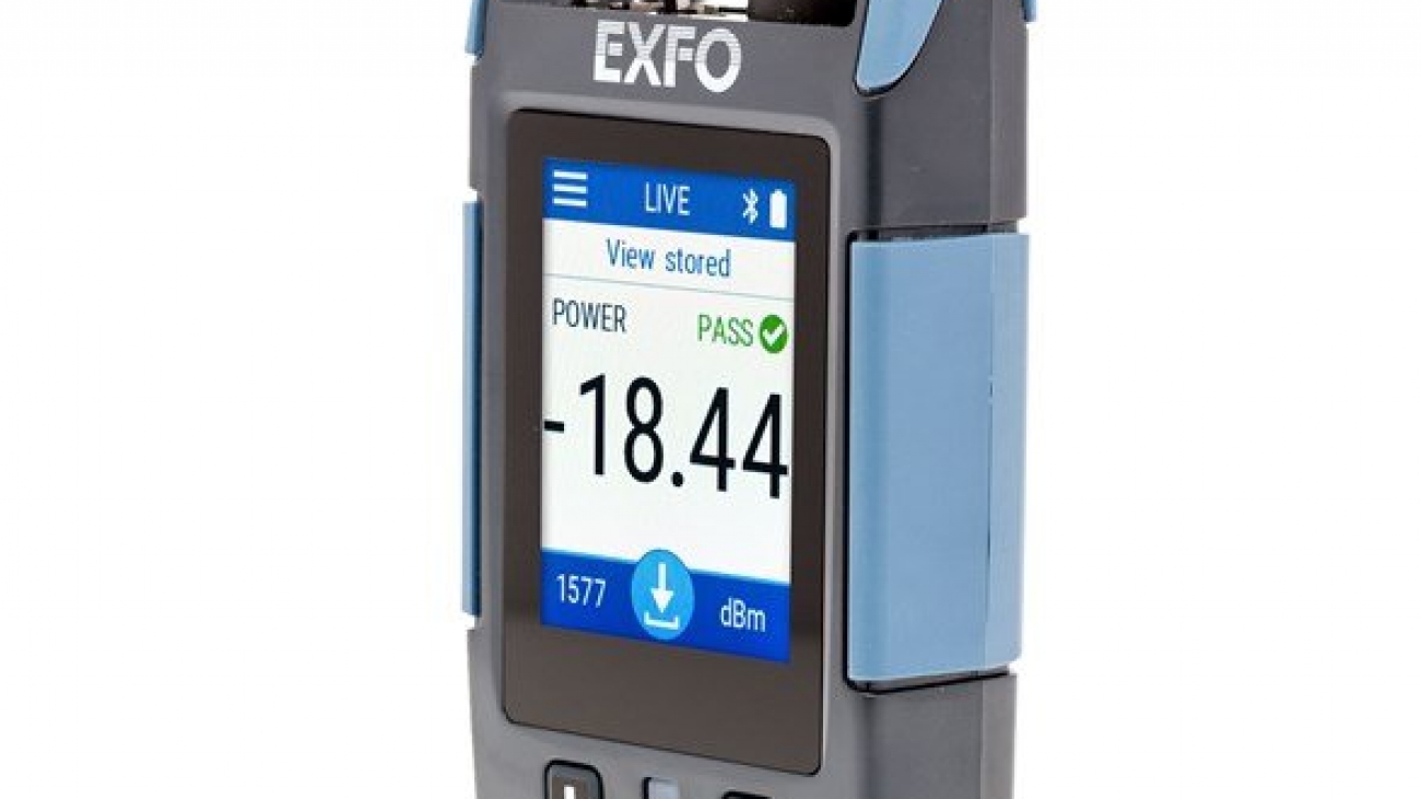
The EPM-50 Power Meter provides highly accurate power measurements, as well as reference value setting capabilities. It offers power autonomy of 300 hours, for reliable, long-lasting performance in the field.

mpc-100_1

MPC-100 – optical power checker

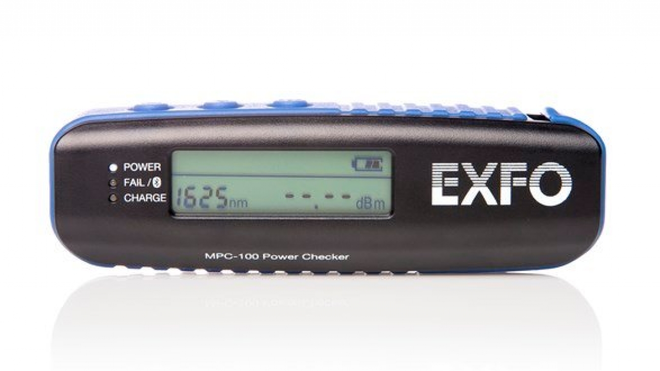
The MPC-100 is an innovative optical power checker enabling smart device connectivity via Bluetooth®. Paired with the FIP-425B or FIP-435B Wi-Fi inspection probes, this easy-to-use power checker lets you take full advantage of smart device connectivity.

You can manage all your results in one place and lower the cost of ownership by utilizing your smart device to its full potential.

pmd-350d_1

PPM-350D – next-gen PON power meter

To provide the right speeds to the right customers, communications service providers (CSPs) are deploying next-gen and legacy passive optical network (PON) technologies by overlaying multiple new wavelengths on existing fibers. This brings new challenges for quick and accurate testing during the critical service activation phase: CSPs need power meters capable of testing next-gen and legacy PON technologies, and their field teams need to be sure they are correctly testing the right technology.

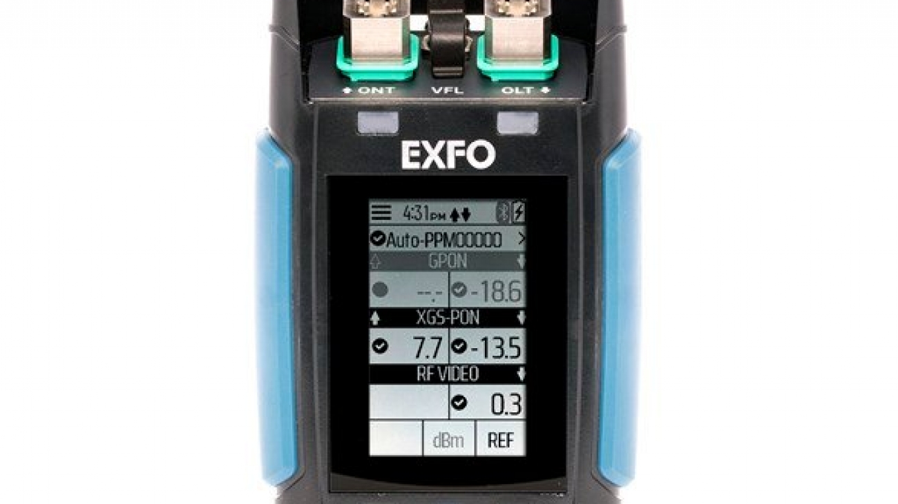
The PPM-350D was designed to tackle both challenges head-on with its unique PON-aware™ technology. Developed in partnership with a Tier 1 CSP, the PPM-350D PON Power Meter automatically detects and adapts test parameters for the PON technology in use at the customer premises, eliminating costly guesswork by field technicians. As a result, service providers can deploy faster, cut activation costs and boost customer satisfaction.

logo_fastreporter-2

FastReporter 2 – data post-processing software

Consolidated data management and post-processing tool that increases reporting productivity for connector endface inspection and all types of optical-layer testing including optical link mapping (iOLM), OTDR, ORL, loss, PMD and chromatic dispersion.

ftb-7400e_1

FTB-7400E – metro/OTDR

No-compromise versatility for metro and long-haul testing

Today’s fiber networks integrate long-haul and metro applications, making OTDR versatility a must. While long-haul architectures require high dynamic range values to reach greater distances, metro links demand an OTDR offering good resolution (short dead zones) due to the proximity of many connection points. Up to now, OTDR users had to compromise on one or the other and buy two units—a choice that they no longer have to make.

The FTB-7400E OTDR combines EXFO’s renowned optical performance and unparalleled software analysis with both short dead zones and high dynamic range values, delivering the versatility needed to test long-haul and metro links with a single OTDR.

With high dynamic range and short dead zones, the FTB-7400E measures end-to-end loss through multiplexers and demultiplexers, helping service providers speed up troubleshooting and maintain first-class quality of service (QoS) standards.

EXFO’s OTDR software: boosting productivity in the field

Auto and advanced modes: choose your testing approach

Streamline data acquisition in the field and report generation back at the office with EXFO’s powerful OTDR software. Choose from two testing approaches: Auto mode or Advanced mode.

Auto mode: one-touch testing

Ideal for basic, repetitive applications, the Auto mode shortens the learning curve for new OTDR users.

  • Preset test parameters
  • Choice of single- or dual-wavelength OTDR testing
  • Convenient one-step event table

Advanced mode: flexibility for experts

For complete control over your test routine, select the Advanced mode. Manually set all acquisition parameters, including the index of refraction (IOR) and helix factor. Save time and get better results by fine-tuning acquisition parameters on the fly.

General OTDR software features

Great display legibility for outdoor work

For installation and maintenance crews, working outdoors goes with the territory. Switch between black and white display backgrounds as needed, and enjoy great legibility, even in the brightest daylight.

Smooth data management

This feature combines file autonaming with subset cable and fiber incrementation.

Universal OTDR compatibility

Based on the universal Bellcore format (.sor, Telcordia SR-4731), the software lets you access OTDR traces from various test and measurement manufacturers. You can therefore use the FTB-200 or the FTB-500 and still refer to your previously archived OTDR files.

FTB-500 platform OTDR software feature

Multiple-trace comparison

Multiple-trace viewing lets you quickly compare traces and detect anomalies within fibers of a tube, a ribbon or even a whole cable.

FTB-200 platform OTDR software features

Summary screen

View—at a glance—the pass/fail status for each tested wavelength. What’s more, the software automatically detects macrobends, which are also displayed in the summary screen.

Linear trace view

This feature virtually eliminates the need to analyze complex OTDR graphs. It provides a straighforward display of all events and related loss and ORL values. Easily toggle between OTDR traces and the linear view.

Fast-track data post-processing with FastReporter software

The optional FastReporter software package provides you with the post-processing tools and functionalities you need to meet such challenges, whatever the application. Designed for off-line analysis of field-acquired data, FastReporter offers a truly intuitive graphical user interface (GUI), which contributes to boosting productivity.

Live templating for OTDR testing

Benefit from one-step file management at any wavelength. Keep full control by adding or removing events manually, or add/remove events automatically using a reference. Get uniform, detailed cable reports.

Powerful batch processing

Automate repetitive operations on large numbers of OTDR test files, and optimize your productivity. Document an entire cable in a matter of seconds. Adjust your cable parameters and detection thresholds and perform batch analysis. Open OTDR files from various vendors’ equipment and convert them to the universal Telcordia format.

Bidirectional batch analysis

Analyze an entire cable in just two steps. View data for all events on all fibers, and at each wavelength, on a single screen.

Flexible reporting

Choose from various report templates, including loss and ORL, OTDR, PMDCD and fiber characterization. Generate comprehensive cable reports in PDF, Excel or HTML format.

Time savers from EXFO’s OTDR viewer software

This free software brings you key data post-processing features such as:

  • Pass/warning/fail threshold setup, which helps you meet ribbon and multifiber validation specifications
  • Bidirectional trace analysis, which provides more accurate, averaged loss measurements for each event
  • Multifiber testing using the Template Trace mode, which dynamically compares new OTDR results with a trace you assign as a reference.
ftb-7600e_1

FTB-7600E – ultra-long-haul OTDR

The FTB-7600E OTDR: for powerful ultra-long-haul testing

When distance is an issue, the FTB-7600E OTDR, with a dynamic range of up to 50.5 dB, is the solution. Taking full advantage of EXFO’s industry-leading expertise in OTDR development, this module can test over distances of up to 200 km.

Thanks to its unmatched linearity of ±0.03 dB/dB, this OTDR accurately locates faults on ultra-long links—without compromising on resolution and distance. It is offered in single and dual wavelength configurations (1310/1550/1625 nm).

This combination of quality and power makes the FTB-7600E an excellent choice for companies deploying and maintaining ultra-long-haul networks.

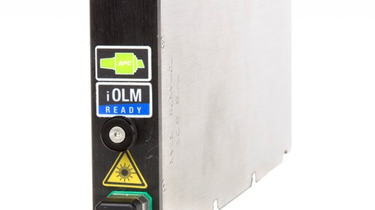
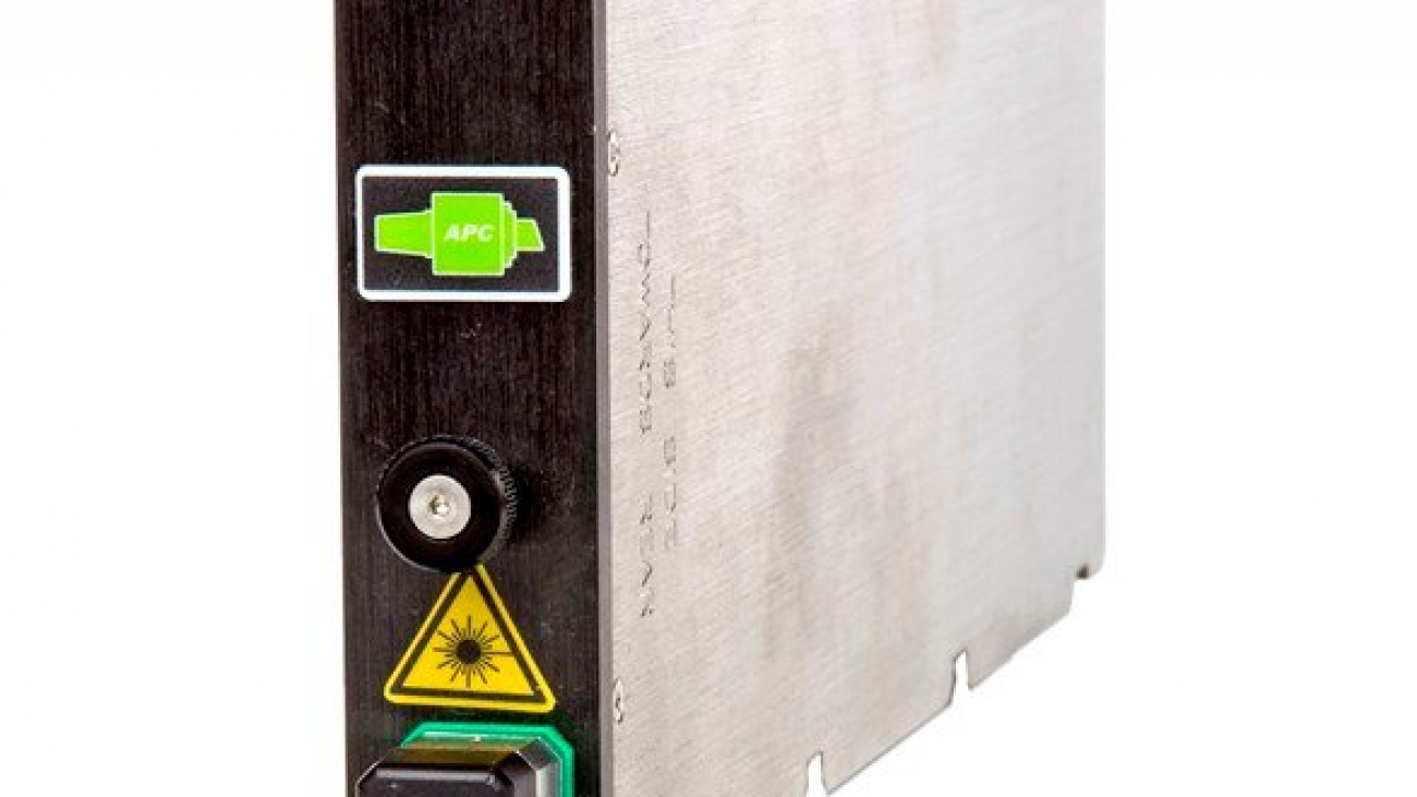
ftb-ltc_psb_spsb-1hr

FTB-LTC/PSB/SPSB – launch test cable/pulse suppressor box

Choice of configurations

Typically, the length of an OTDR’s dead zone is equivalent to that of the optical pulse plus a few meters. The chosen launch test cable should therefore be longer than the pulse dead zone used for the tests. For instance, a 1 µs pulse is approximately 100 m long; selecting a 150 m SPSB or a 300 m LTC/PSB would therefore be appropriate.

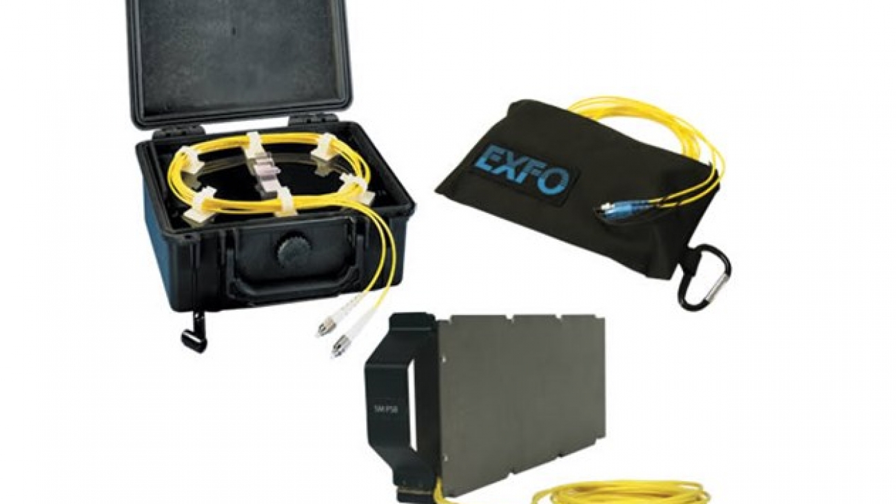
EXFO offers three types of launch cables:

  • The FTB-LTC module combines with an FTB-7000 series OTDR module in the FTB-500 or FTB-200 platform
  • The stand-alone PSB comes in a rugged, compact carrying case
  • The portable SPSB comes in a soft, easy-to-carry-everywhere pouch

How it works

Link characterization is often performed using an OTDR. But even though an OTDR has the shortest dead zones, because of the way loss is measured in a link, it does not allow the characterization of the first and last connectors without using a launch test cable, also called a pulse suppressor box. Here’s why.

The loss value associated with an event is the difference between the backscattering levels measured before and after the event. To account for the OTDR’s dead zone, obtaining a backscattering level before the first connector requires inserting a certain length of fiber between the OTDR port and the first connector of the fiber under test. At the other end of the link, the same length of fiber is added after the last connector of the “receive” cable.

In order to obtain an accurate, complete picture of the system’s loss—which is a critical aspect of fiber commissioning—a launch test cable should always be used at both ends of the fiber link.